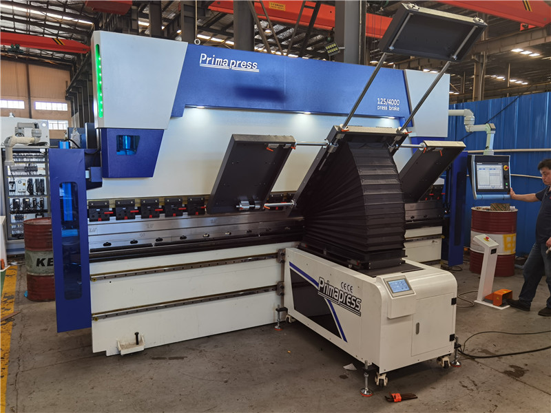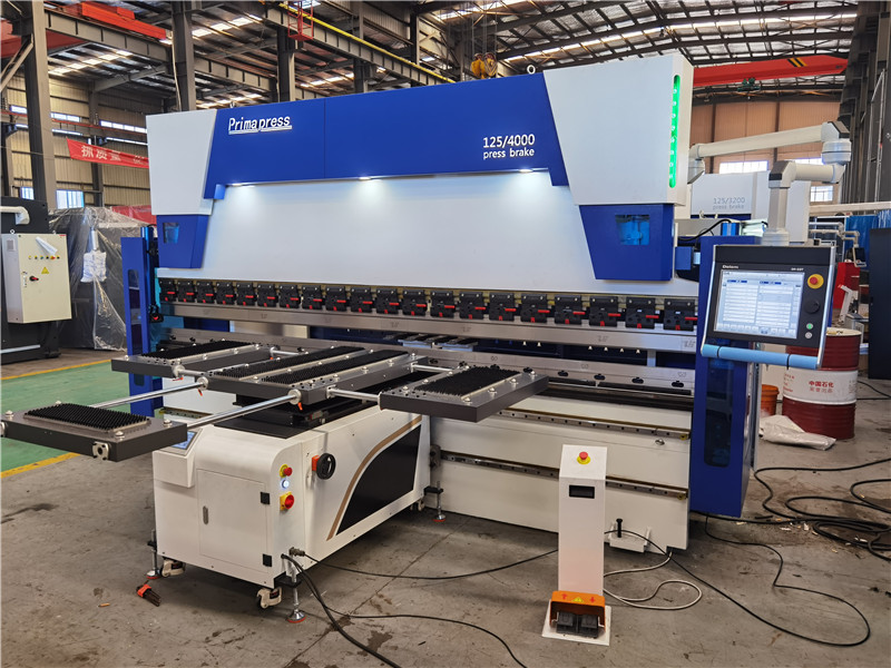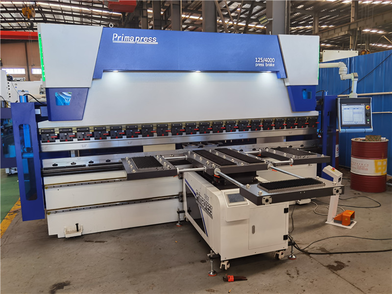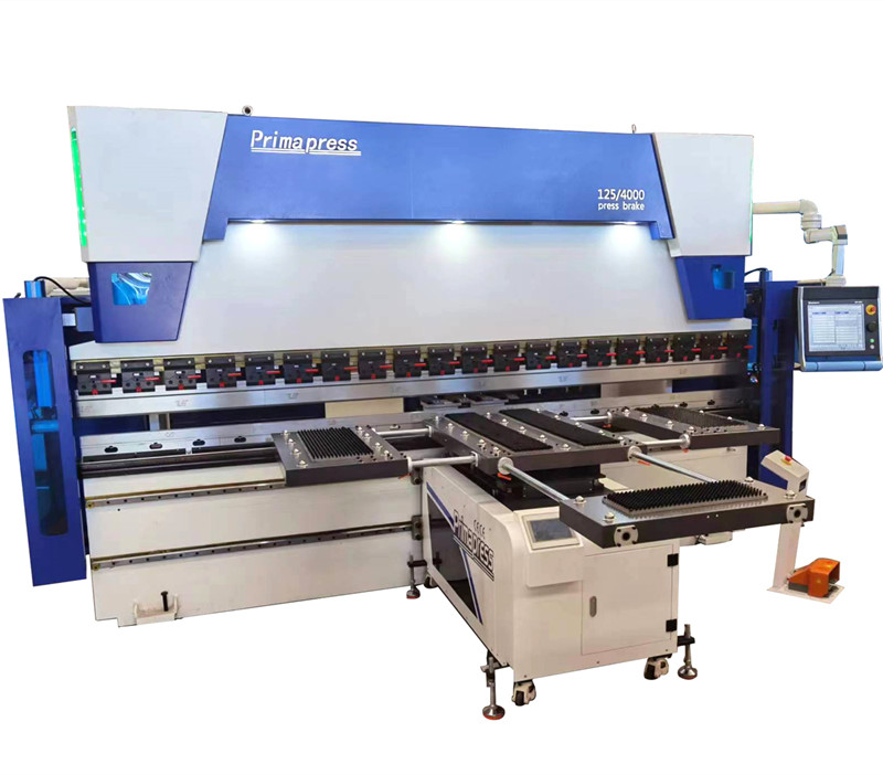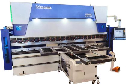
Electro-hydraulic servo CNC press brake bending machine follow-up front automatic support arm
Electro-hydraulic servo CNC press brake bending machineis a bending machine in which the servo motor is used as the actuating device, and the numerical control system combines the feedback data of the grating scale to control the flow ratio of the main oil cylinders on both sides to achieve the synchronous movement of the slider. In addition, the bending machine forms a closed-loop control, the feedback is accurate, and the sliding block runs accurately, so that the bending accuracy and the repeated positioning accuracy of the sliding block are high. Do you know the performance characteristics of this bending machine? If you are not sure, take a look at the following introduction.
Regarding the performance characteristics of the electro-hydraulic servo CNC bending machine, the following is a detailed introduction:
- The electro-hydraulic servo CNC press brake bending machineadopts a hydraulic convex automatic compensation system to solve the influence of the deformation of the slider during the bending process on the quality of the workpiece. The amount of compensation is automatically adjusted by the numerical control system, which is convenient and accurate.
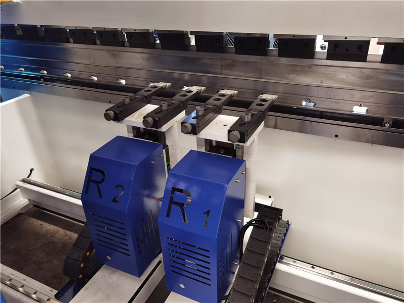
- The electro-hydraulic servoCNC press brake bending machineadopts a fully functional back gauge mechanism, which can optionally control multiple back gauge shafts. Functional parts in the back gauge. Such as guide rails, lead screws, bearings, etc. are all imported originals to ensure the accuracy of the back gauge.
- The body of the electro-hydraulic servoCNC press brake bending machineadopts an integral welding structure, which is convenient for transportation and processing, and can ensure the overall accuracy of the machine tool.
- The fuselage, slider and other important components of the electro-hydraulic servoCNC press brake bending machineare analyzed by ANSYS finite element analysis software to ensure the reliability of the machine tool.
- The hydraulic system of the electro-hydraulic servoCNC press brake bending machinereduces the installation of pipelines, improves the working stability of the machine tool, and has a beautiful and simple appearance.
The power drive of the mechanism is mainly given by two servo motors. For different sizes of molds, in order to make the upper and lower sides of the flap of the front support mechanism on the same level, the servo motor can transmit power through the pulley to drive the lead screw to drive the entire slide to move up and down.
Bending machine follow-up front support device
The follow-upCNC press brake bending machineis convenient and quick to operate and has high processing accuracy. Reduce work intensity and improve work efficiency. The front support device of theCNC press brake bending machinecan be customized according to customer requirements, which is convenient for high-quality bending processing.
The working principle of the follow-up support mechanism of the bending machine
Another servo motor installed on the sliding seat drives the lead screw to rotate with the help of the pulley. At the same time, a long key slot is opened on the lead screw, and a latch is installed at the top dead center of the key slot. The rotary motion of the lead screw becomes the lead screw moves up and down along the long keyway opened by itself under the action of the bolt, thereby driving the flap to complete the circular motion around the fixed point, so that the flap can be tightly bent at all times. Sheet metal, let the sheet metal complete a complete bending process.
The left and right movement of the front support mechanism is to manually push the entire follow-up front support mechanism to move along the linear guide rail installed at the front end of theCNC press brake bending machinetable. The operator can push the sheet metal bending work at will, which can be achieved Double use can also be used alone, according to the width of the board to judge the use.
In order to meet market demand, major brands of sheet metal bending machines have successively launched various models of follow-up front support mechanisms. On the whole, most of the follow-up front support mechanism adopts the crank connecting rod mechanism controlled by electro-hydraulic servo. The action of the crank connecting rod mechanism relies on the numerical control system to control the opening size of the proportional servo valve to adjust the amount of oil in the cylinder, thereby controlling the synchronization of the moving speed of the carrier and the bending speed of the sheet. Relatively speaking, its mechanical action is complex, and hydraulic cylinders are required for electro-hydraulic control. The manufacturing cost is high, and the motion trajectory is difficult to control. Wuxi Shenchong feels the whole structure of the front feeding mechanism: the power drive of the mechanism is mainly given by two servo motors. For molds with different heights, in order to keep the upper plane of the front support mechanism flap and the upper plane of the lower mold on the same level, the servo motor can transmit power through the pulley to drive the lead screw to drive the entire slide to move up and down.
In the process of sheet metal processing, the bending of large plates has always been a headache. Because the size of the plate is relatively large and the weight of the plate is relatively large, it often takes 3 to 4 people to fold a workpiece, which costs a lot of money. Not to mention the manpower, the precision of the workpiece produced by doing this is relatively low, and the operator is also relatively tired. The follow-up material support device solves this problem very well, which not only saves labor, but also improves production efficiency, and the precision of the workpiece is also much higher.
The supporting wheel frame of the Primapress bending machine adopts the mechanical transmission technology of the lead screw and the pull rod. During the use of the supporting wheel frame, it is necessary to ensure that the supporting plate is flush with the upper plane of the lower mold. When using molds of different heights to raise or lower the supporting wheel frame, by pulling the rotating handwheel, the rotating handwheel and the left and right rotating lead screws are connected in the middle position. It is connected with the right-handed threaded nut, and the left- and right-handed threaded nut is connected with the lifting rod of the supporting wheel frame. During the rotation of the rotating handwheel, the left and right-handed screw nut is driven to move in opposite directions on both sides by the rotating thread of the left and right rotating screw.
